If a tree dies, plant another in its place.
—Carl Linnaeus
In my last article, I gave a general overview of the Device Tree format, and some basics on how it is being used for automatically configuring the hardware of embedded computing platforms like the Beaglebone Black, Xilinx Zynq, and many other System-on-Chip (SOC) devices. Device Tree Overlays, originated by Pantelis Antoniou are now being used to support add-on devices and expansion boards, allowing automatic discovery and automatic configuration on several computing platforms. In this article, I'll discuss the Device Tree Overlay and why it is getting adopted for even more computing platforms.
The DeviceTree format has been employed on several Linux based computing platforms, such as the PowerPC, or Power Architecture for several years now. However, add-on and expansion boards typically had either no automatic configuration support, or used other description structures like the IPMI FRU blob, or the TEDS blob (for sensors). However, as hardware becomes more maleable, using Field Programmable Gate Arrays, and Programmable System-on-Chip devices, the hardware begins to "soften", and to resemble software. "Hardware" said Pantelis Antoniou at LinuxCon2014, "is software now". So the concept of a static and unchanging Device Tree wasn't keeping pace with the new programmable hardware paradigms, and Pantelis originated the idea of a Device Tree Overlay that could be dynamically loaded and unloaded to change hardware configurations. It has taken some time (and a lot of work by Pantelis and others) to make all the Linux kernal and Device Tree Compiler changes required, but now, most of their work has been merged into the 3.17 Linux Kernal.
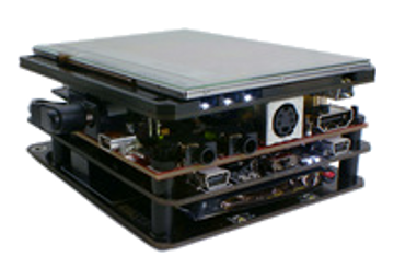
 Consider a typical development situation, using something like a Beaglebone Black,
where you have a main CPU/SoC board, and several expansion boards (i.e. "Capes") attached,
similar to the picture to the right. For the sake of discussion, let's say that Cape #1 communicates with the
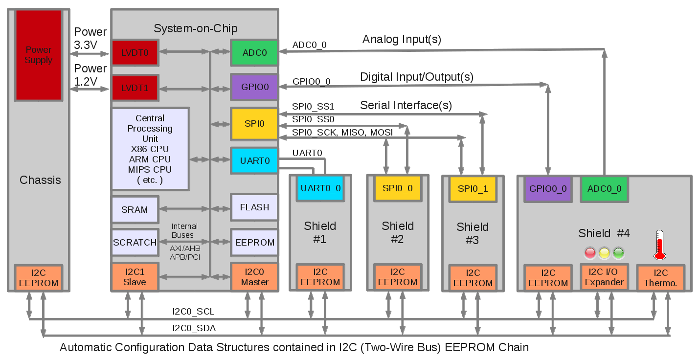
main CPU/SoC via a serial UART interface, Cape #2 and #3 communicate via a SPI interface with separate
Chip Selects for each Cape, and that Cape #3 communicates using General Purpose I/O (GPIO),
and the main CPU/SoC Analog-to-Digital converter (ADC). In order to support the Device Tree
configuration, each board/Shield will contain a small I2C EEPROM that will hold the Device Tree
Flattened Device Tree data structures (i.e. the Overlays). This is a fairly common configuration,
and it doesn't really matter WHAT the Capes are for this discussion, they could be peripherals
like LCD displays, Wi-Fi Radios, Motor Controllers, Sensor Hubs, etc. We're interested here in
describing their interconnections, which can be represented by the block diagram below :

As you can see in the above block diagram, the "orange" colored blocks represent the connections on the I2C bus that will be used to read the Flattened Device Tree data structures (i.e. the Overlays) for each expansion board (i.e. Cape/Shield/Plate), in order to determine their make and model, and how they are interfaced and connected.
Device Tree Source Overlay
Alright, so let's look at what a Device Tree Source Overlay might look like for Cape #1, which is connected via a serial port, namely UART0. For this example, we'll use the Circuit Co. RS-232 Cape as an example of a currently used Device Tree Overlay.
1
2
3
4
5
6
7
8
9
10
11
12
13
14
15
16
17
18
19
20
21
22
23
24
25
26
27
28
29
30
31
32
33
34
35
36
37
38
39
40
41
42
43
44
45
46
47
48
49
50
*
 * Copyright (C) 2013 CircuitCo
 *
 * Virtual cape for UART1 on connector pins P9.24 P9.26
 *
 * This program is free software; you can redistribute it and/or modify
 * it under the terms of the GNU General Public License version 2 as
 * published by the Free Software Foundation.
 */
/dts-v1/;
/plugin/;

/ {
   	compatible = "ti,beaglebone", "ti,beaglebone-black";

        /* identification */
        part-number = "BB-UART1";
        version = "00A0";

        /* state the resources this cape uses */
        exclusive-use =
                /* the pin header uses */
                "P9.24",        /* uart1_txd */
                "P9.26",        /* uart1_rxd */
                /* the hardware ip uses */
                "uart1";

	fragment@0 {
                target = <&am33xx_pinmux>;
                __overlay__ {
                        bb_uart1_pins: pinmux_bb_uart1_pins {
                                pinctrl-single,pins = <
					/* P9.24 MODE0 OUTPUT (TXD) */
					0x184 0x20
					/* P9.26 MODE0 INPUT  (RXD) */
					0x180 0x20
                                >;
                        };
                };
	};

	fragment@1 {
                target = <&uart2>;	/* really uart1 */
                __overlay__ {
                        status = "okay";
                        pinctrl-names = "default";
                        pinctrl-0 = <&bb_uart1_pins>;
                };
        };
};
The first properties define our "compatible" properties, and the part number and version. This is followed the "exclusive-use", which defines what resources we want to utilize exclusively. Then comes the pin multiplexing definitions, and finally our "uart0" definition. Once compiled, using the Device Tree Compiler, the resulting Flattened Device Tree binary overlay can be written into the I2C EEPROM located on Cape #1 (or Shield #1, PiPlate #1, etc.). Don't worry too much if you don't follow all the exact syntax details yet, we'll cover more on these concepts in the detailed how-to articles for each specific platform.
Automatic Device Discovery
After a reboot, the connections and interface to Cape #1 can be automatically discovered and configured. How, you ask? Well, during the boot up sequence, the processor reads the Flattened Device Tree binary from it's local EEPROM (or it's internal flash memory), and using the main Device Tree, configures it's I2C controller (shown in "orange" in the above block diagram), and then starts to read the contents of each of the remote EEPROMs, located on the expansion cards, one at a time, by expecting them to reside at the following addresses on the I2C bus.
| A2 | A1 | A0 | I2C Address | Device |
| 1 | 0 | 0 | 0x54 | Shield #1 (Beaglebone Cape #1) |
| 1 | 0 | 1 | 0x55 | Shield #2 (Beaglebone Cape #2) |
| 1 | 1 | 0 | 0x56 | Shield #3 (Beaglebone Cape #3) |
| 1 | 1 | 1 | 0x57 | Shield #4 (Beaglebone Cape #4) |
As the microprocesser reads each I2C EEPROM from each expansion board in turn, it looks for the "magic number" of "0xd00dfeed (big-endian)" in the first word of each EEPROM. If the microprocessor finds the that "magic number", it assumes the EEPROM contains a Flatten Device Tree data structure, and begins to read it and check it for validity. Once the microprocessor determines that it contains a valid structure, it begins to install the devices/device drivers.
Device Tree Overlay Pin Multiplexing
One of the things you might have noticed about the Device Tree Overlay is the specificity of the Pin Multiplexing directives. Most modern System-on-Chip (SoC) devices have several functions available per pin for application flexibility, and we need to define what pins are going to be used to connect to the peripherals. Unfortunately, the scheme adopted in the Device Tree Overlay is highly specific, and tied to the particular processor model used (in this case the AM335X series). In order to support a wide variety of peripherals attached to a wide variety of different processors, it might be better to adopt a more "virtual approach" to I/O pin assignments. I'll go into this in more detail over the next several articles.
Summary
This has been a very brief introduction to the Device Tree Overlay concept, used for automatically configuring the hardware of embedded computing platforms like the Beaglebone Black, Xilinx Zynq, and many other System-on-Chip (SOC) devices. Support for the Device Tree is still evolving, and much work remains to be done to foster widespread acceptance on other platforms. If you are looking for a specific how-to guide for BeagleBone, Raspberry Pi, Xilinx, Altera, etc, please see the References section at the end of this article for a complete listing. A number of people in the community have already written some excellent guides and instructions for specific platforms.In upcoming articles, I'll be making some suggestions for the Device Tree and Device Tree Overlays, in order to add features like manufacturing traceability, calibration, virtual I/O, and testing.
References, Footnotes, and more Device Tree information...
- Device Tree for Dummies - Thomas Petroni
- BeagleBlack Device Tree Tutorial - Adafruit
- Xilinx Device Tree Tutorial - Xillybus
- Altera Device Tree Tutorial - Xillybus
- ARM Device Tree Support - Ubuntu
- Altera Device Tree Support - Altera
- Index of Device Tree Bindings - kernal.org
- Device Tree Graphing - kernal.org
- libfdt - manipulating FDT Blobs - David Gibson
- Linux Bootloaders - informit.com
- Device Tree PnP - Eli Billauer
- Device Tree Overlay Manager - Pantelis Antoniou
- Device Tree Overlay Proposal - Grant Likely
- BeagleBlack Univeral I/O - cdsteinkuehler
- BeagleBlack Device Tree Overlay Generator - Kilobaser
- GPIOs on the Beaglebone Black using the Device Tree Overlays- derek molloy
- Supporting 200 Different Expansion Boards - elinux.org
- DT, The Disaster so Far - Mark Rutland
- Board File to Device Tree Migration - Pantelis Antoniou
- Device Tree Overlays - Jonathon Corbet